DIY PROJECT: TURBO-CHARGE YOUR TR-606
-------------------------------------
The Roland TR-606 has been said to lack the depth and bottom end of its
808 and 909 siblings - the bassdrum makes a popping sound and the snare
sounds a bit like split peas on a tin tray.  But what the 606 does have
going for it is idiot-prof programming and an input for sync24, which can
be easily and cheaply interfaced with MIDI, and all of this is bundled up
in lovely '80s retro grey plastic with loads of LEDs and knobs.
When I started out making music the 606 was my first drum machine, and I
would spend hours trying to get a where the bassdrum would cut enough to
be heard [we all recgonize this don't we? - ed].  After some time I got
really frustrated so I obtained a circuit diagram and made some
modifications.  What transpired was what I've now renamned 'The Mix 06'.

SOME TIPS ON TAKING THE 606 APART
---------------------------------
1. Remove the batteries.
2. Remove the knobs from the front panel.
3. Remove the six screws from the back panel,
   one of which is located in the battery box.
4. Pull the back panel off and unsolder the
   connections to the battery terminals.
5. Remove the two screws located in the battery holder.
   This should now allow you to remove the front panel.
6. Remove the plastic pots which hold the switch board
   to the main PCB. This is done by squeezing the top of
   the pots together with a pair of pliers. You should
   then be able to gently tease the circuit board off,
   which will give you access to the main PCB board. Be
   careful not to snap any of the wires.

PARTS LIST
----------
CAPACITORS
1x 68 nF capacitor
2x 82 nF capacitor

RESISTORS
1x 47 ohm resistor
2x 47K resistor
2x 330K resistor
1x 4.7K pot linear
3x 100K pot linear

SEMICONDUCTORS
1x BC108 transistor
All of the components used in this modification are easily soldered to the back of the PCB, so no extra circuitboards are required, but you will have to drill in the 606 box to bring the wires out to the pots. The box for the pots should also be metal and connected to ground, with the ground point in the 606 being on the large solder joints that hold the drum level pots to the PCB. These are quite easy to recognize.
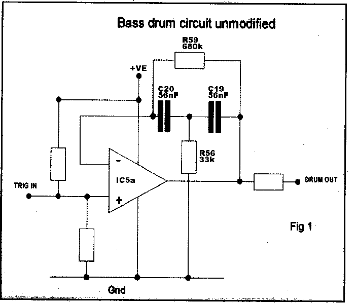
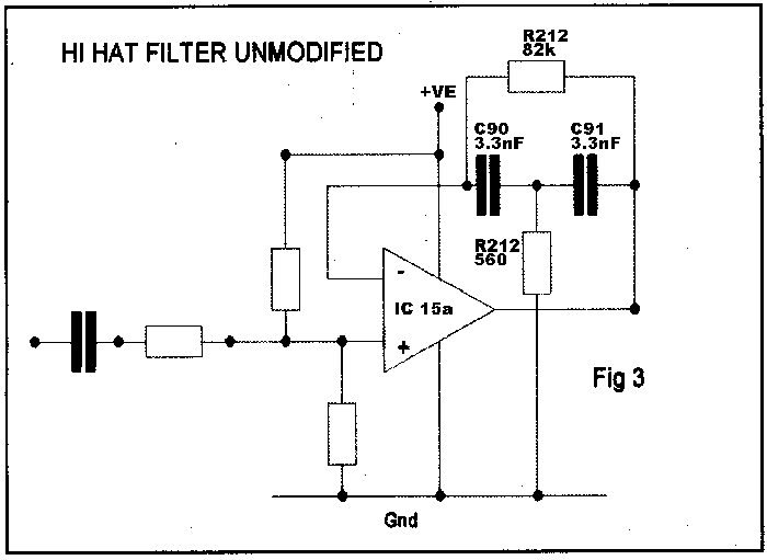
NB: The resistor on picture hi1.GIF (the 3rd from the top) refered to as R212 with the value 560 ohm is in fact R223.
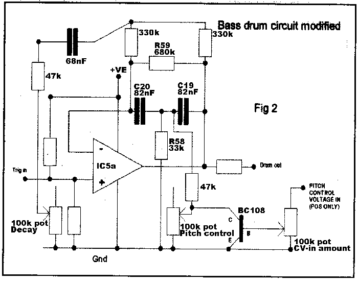
bassdrum mod instructions
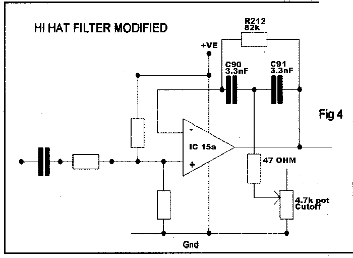
hihat mod instructions


